Seismic Bracing


Solutions for Building Services


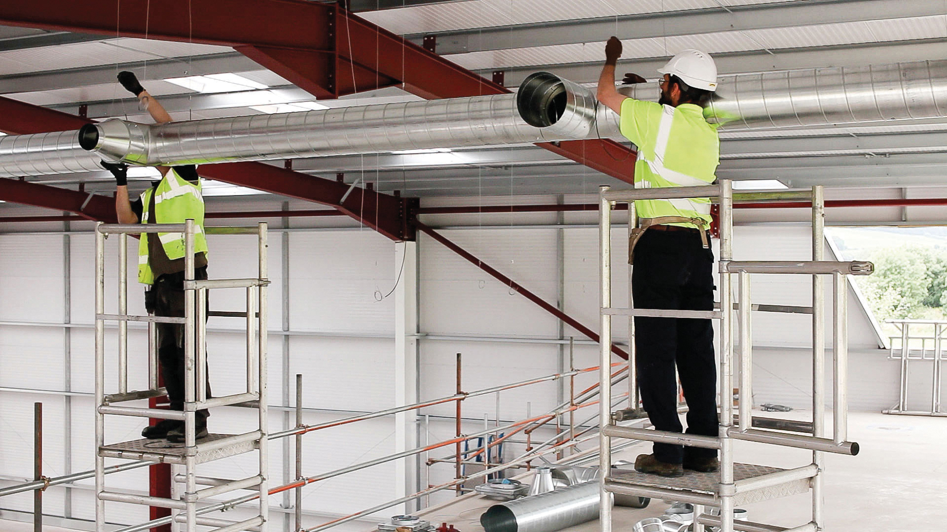
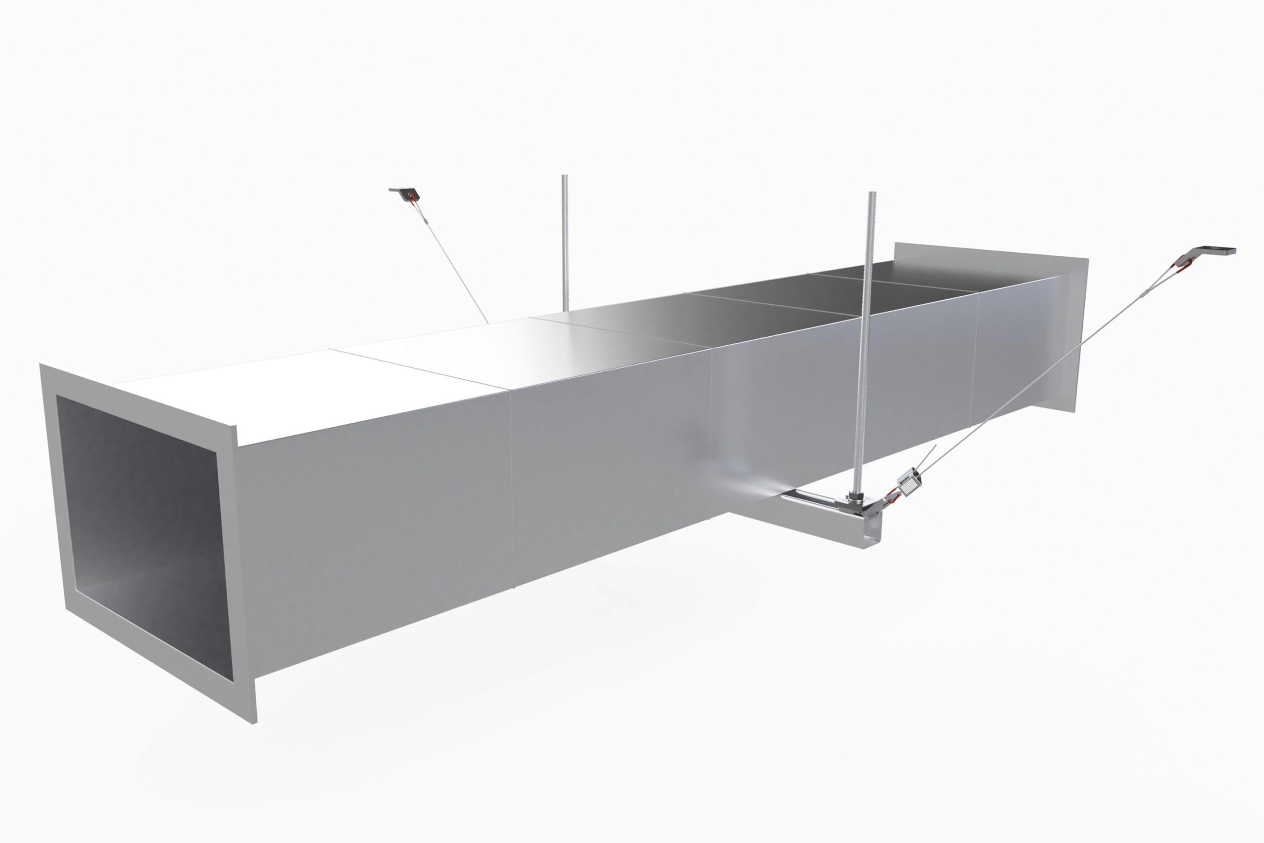
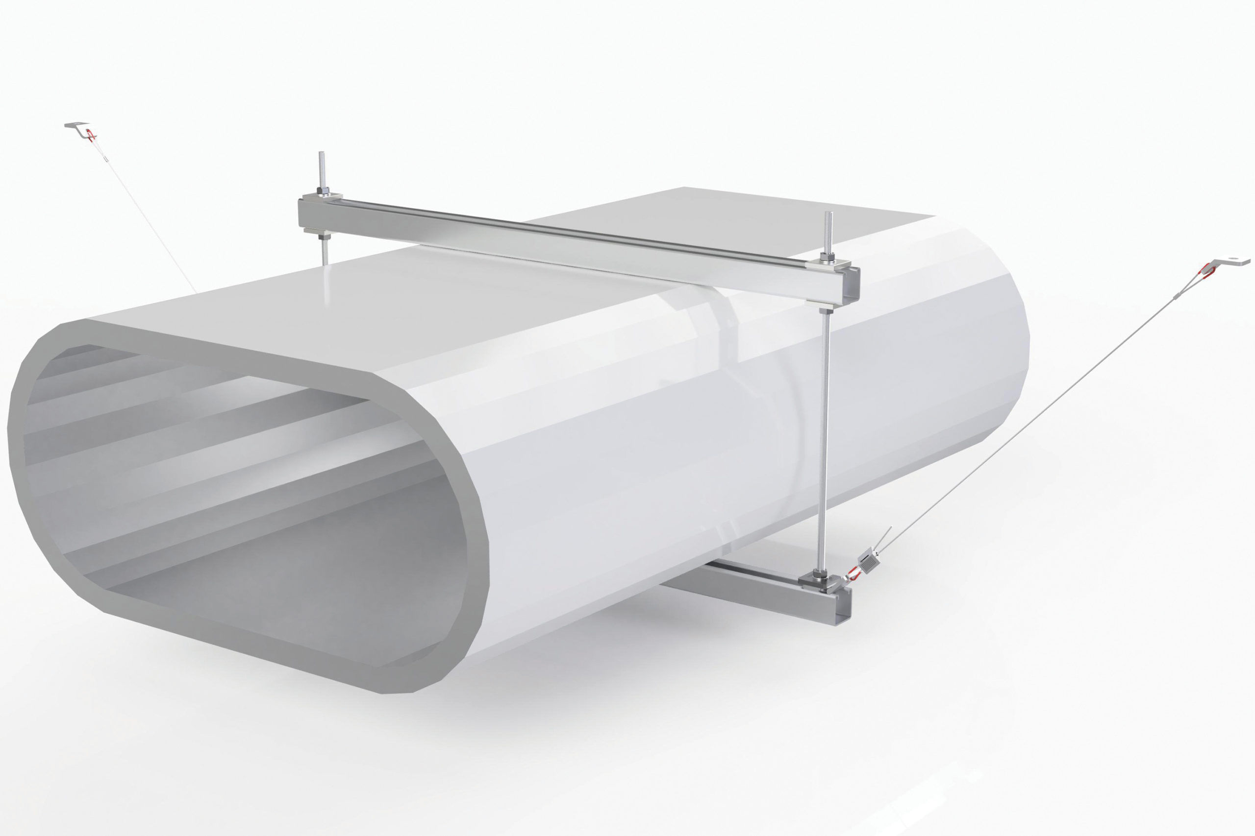
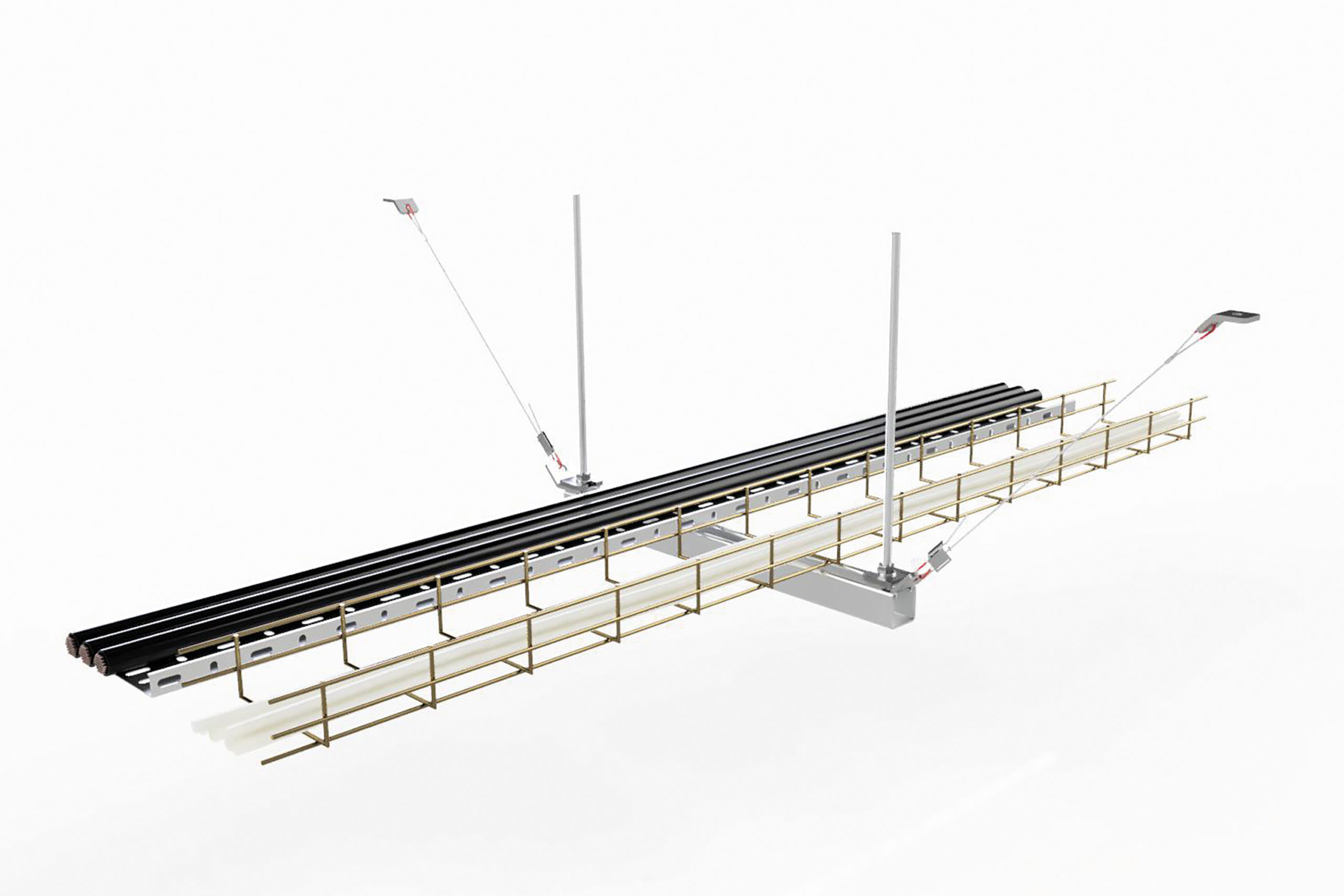
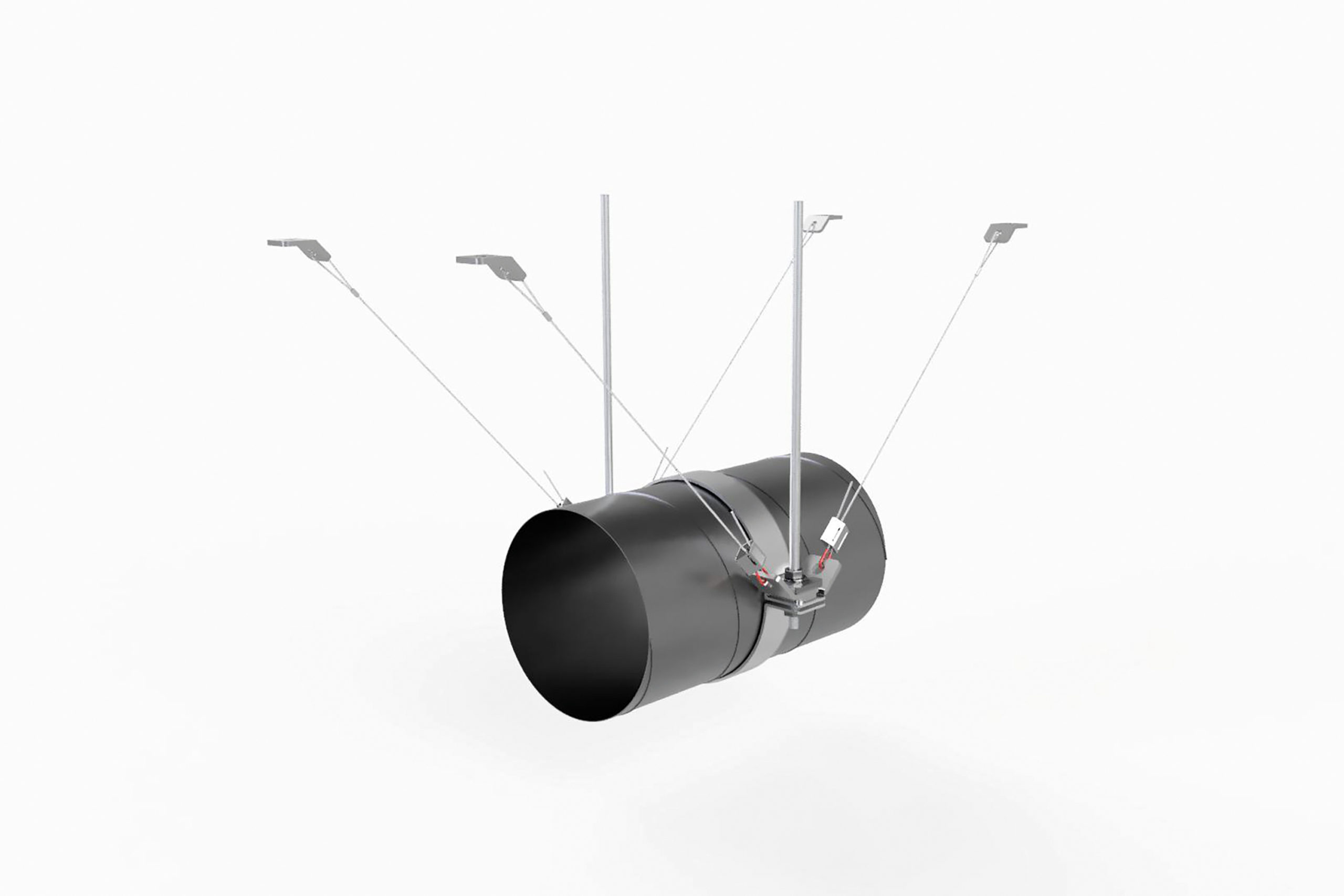
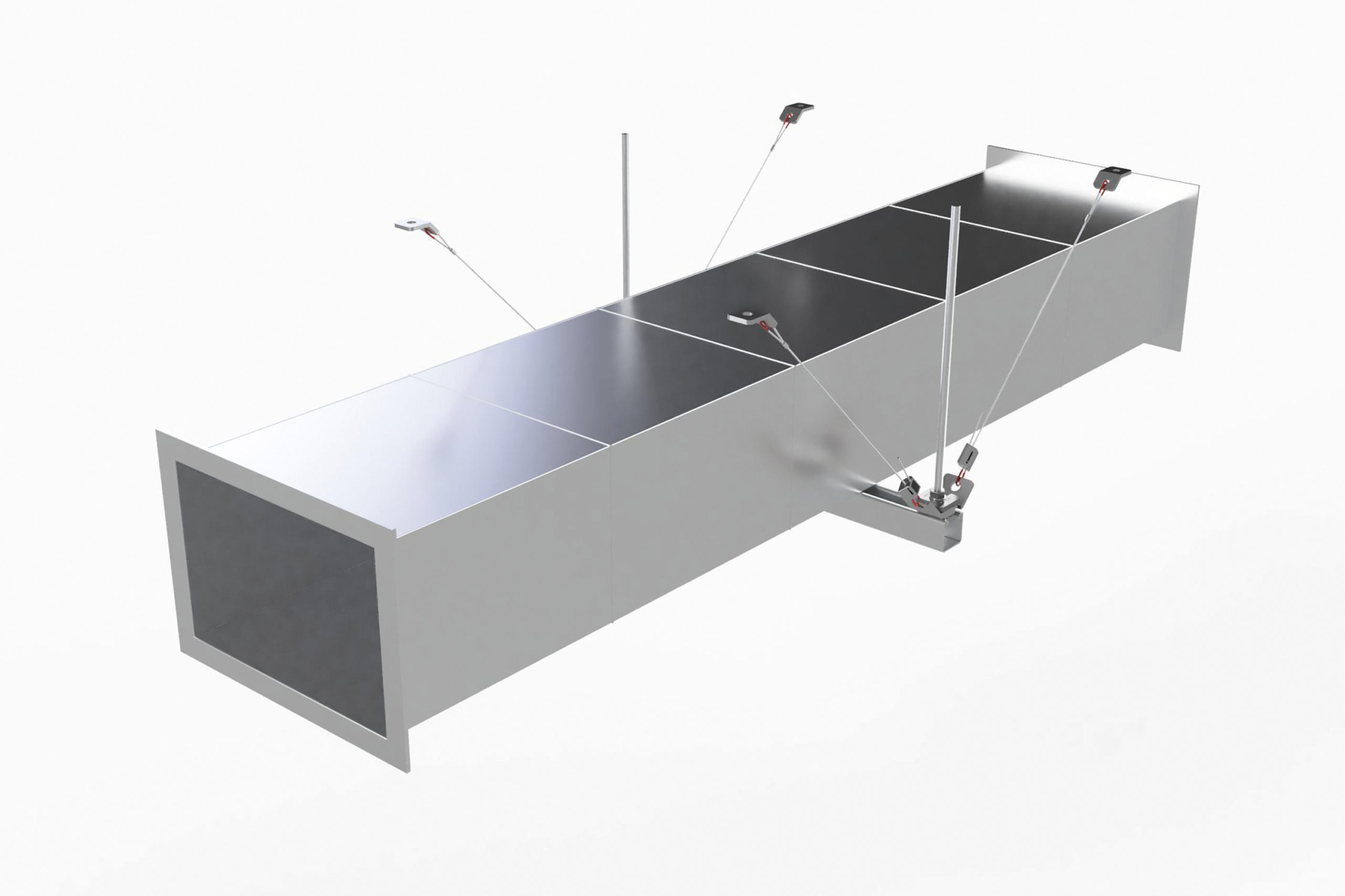
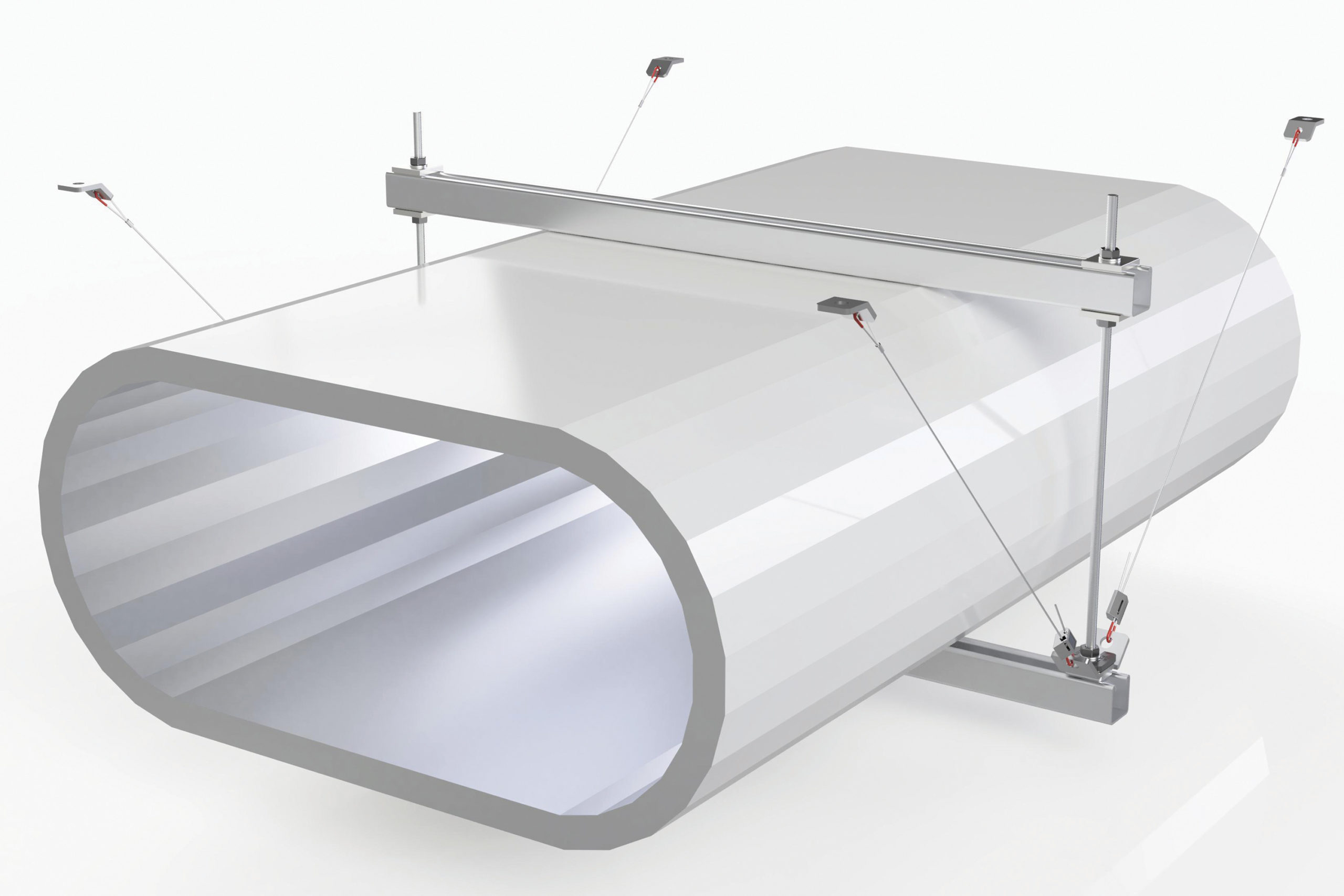
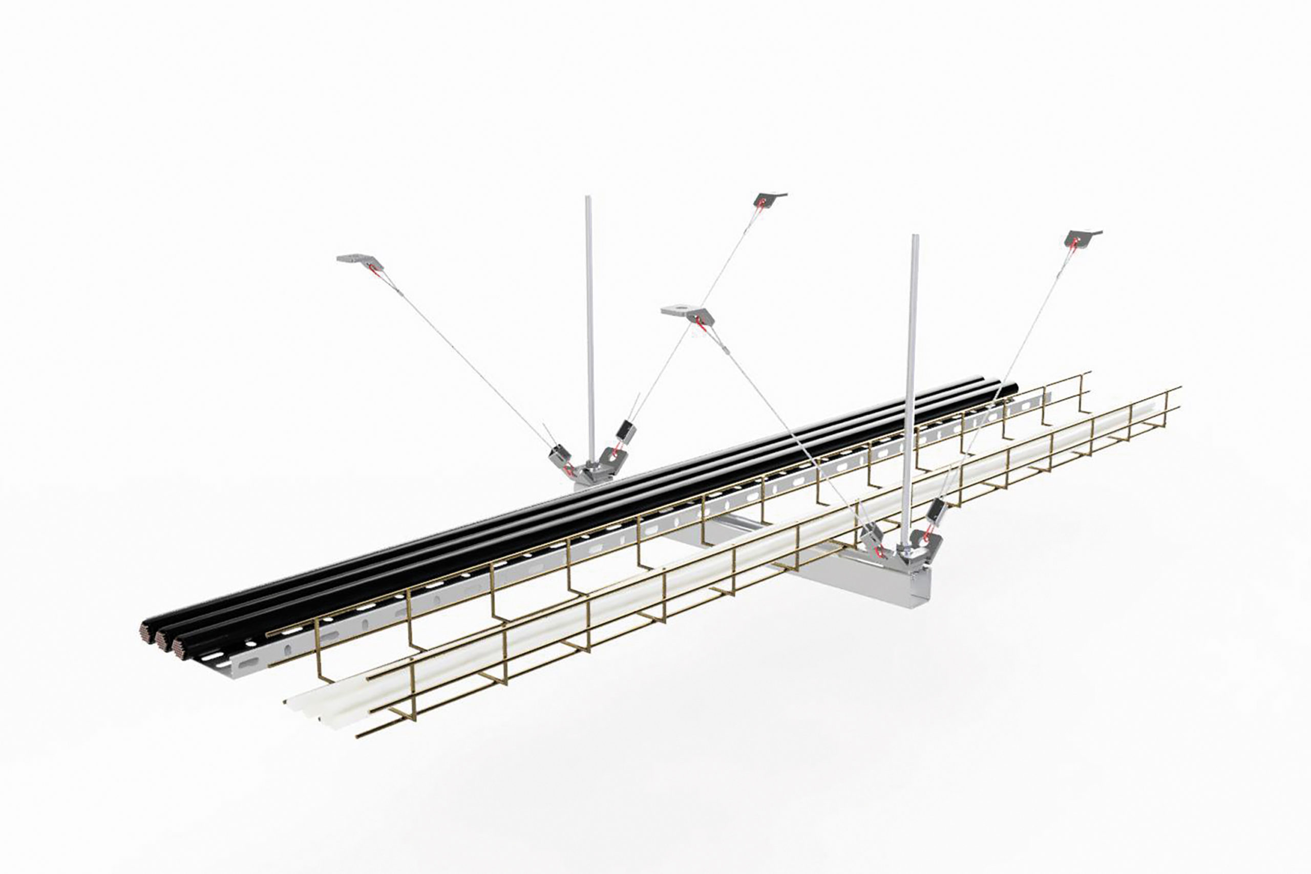
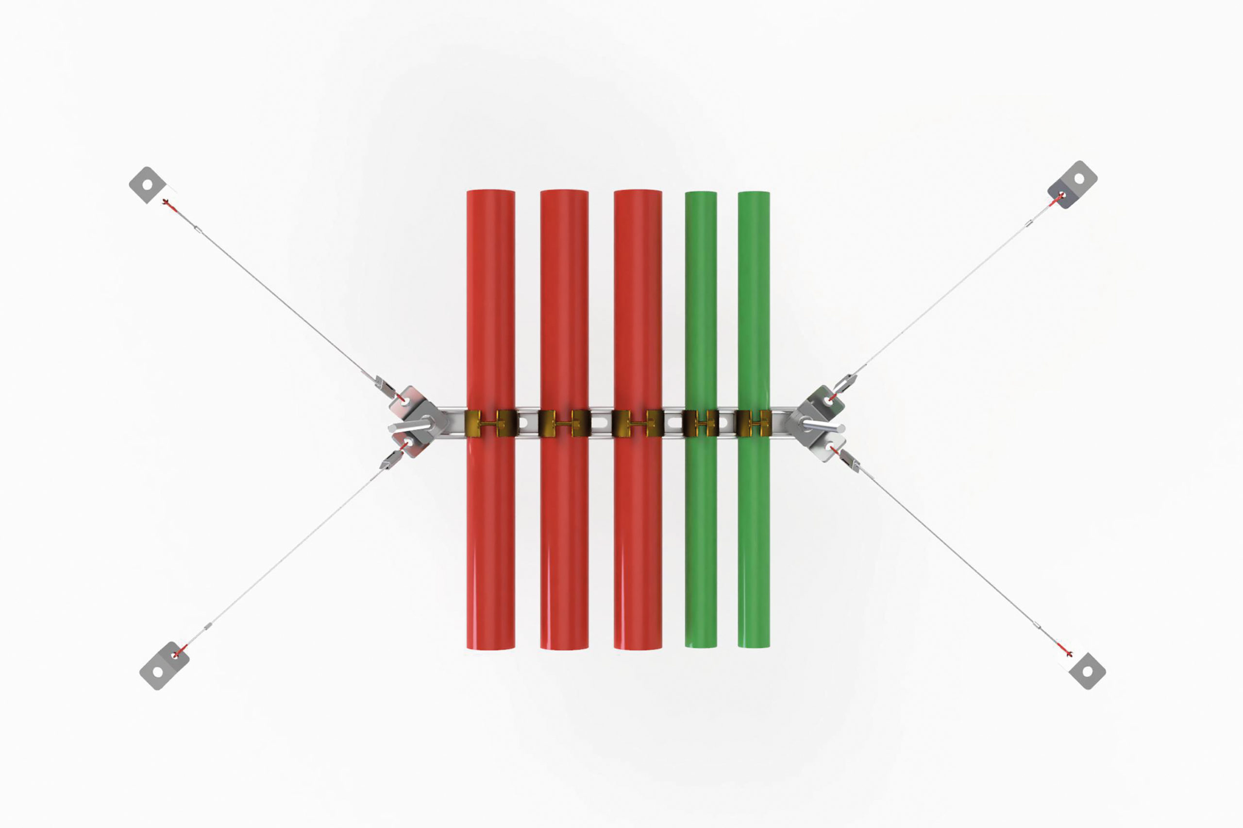
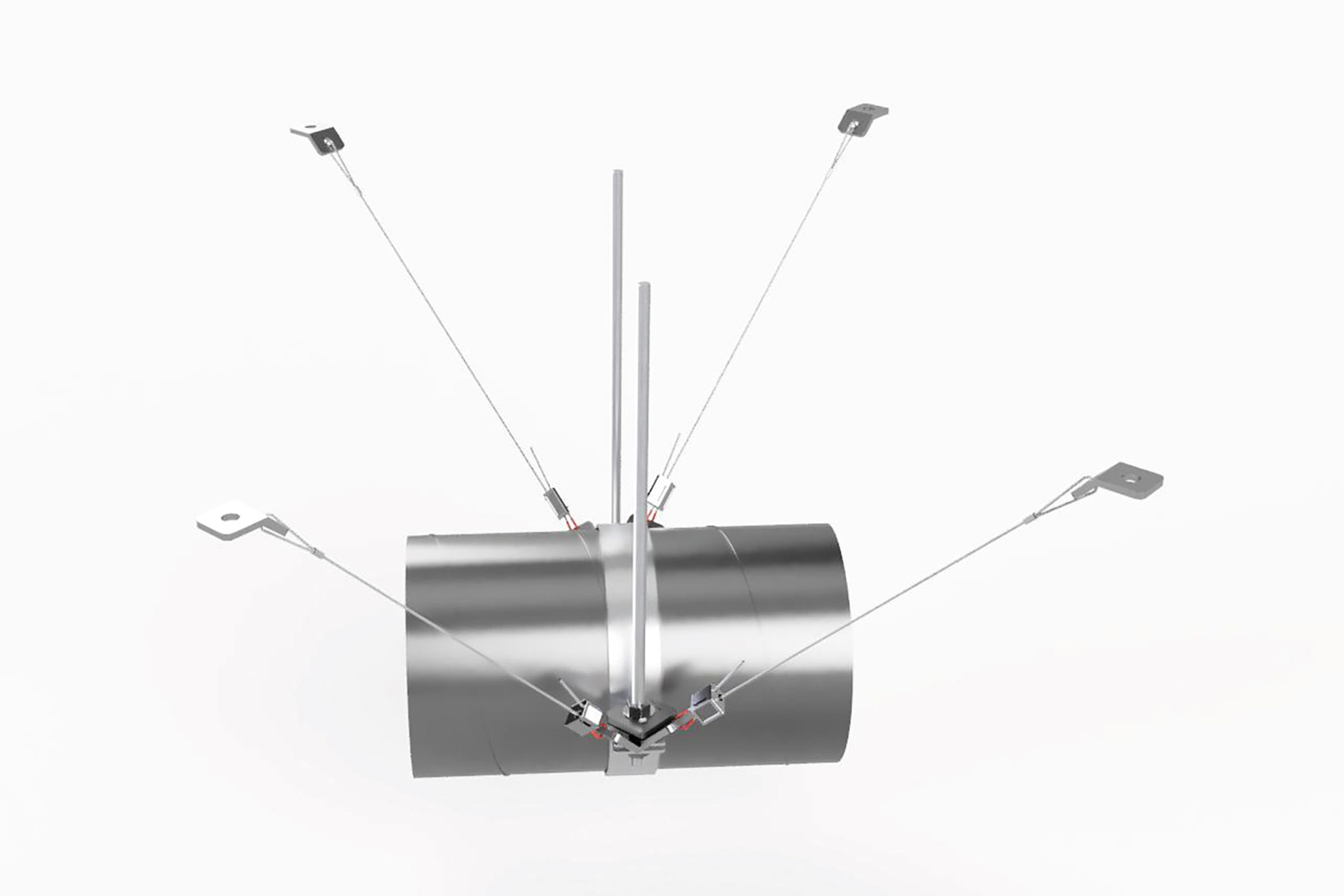
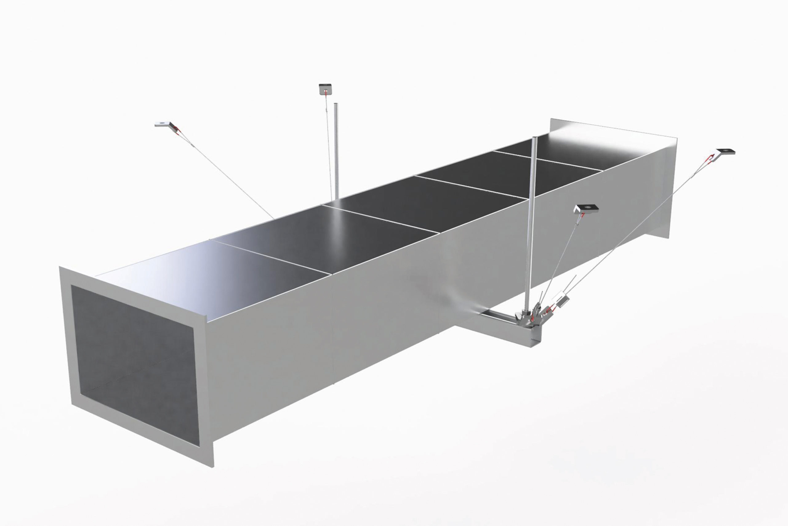
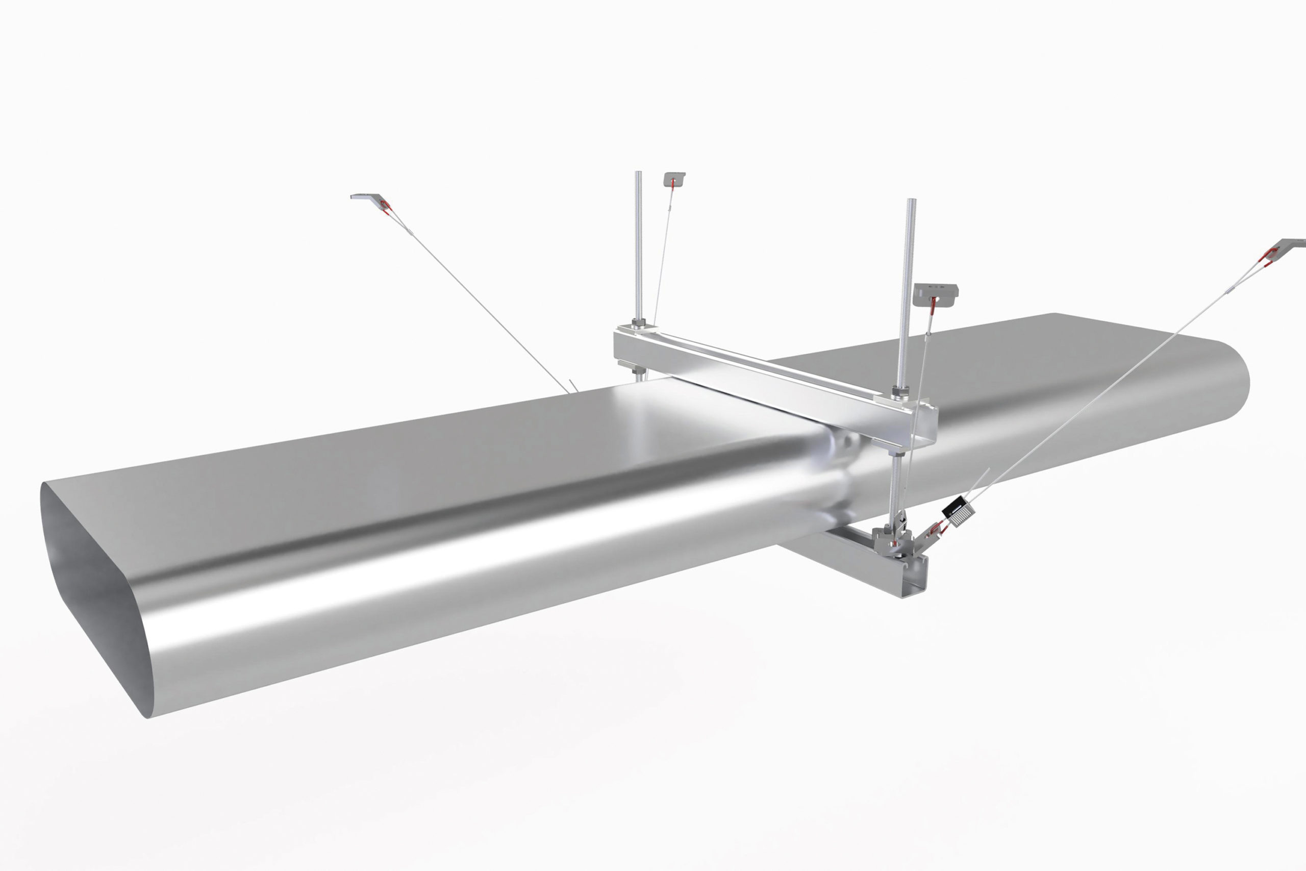
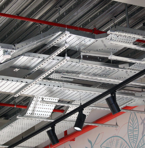
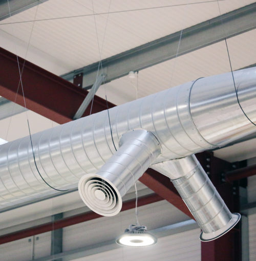
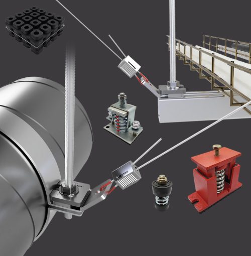
Zip-Clip Seismic Bracing Systems offer a simple and engineered solution to brace and secure non-structural building services, improving the resilience and safety of buildings in the event of an earthquake. This website provides an overview of the bracing systems available. Also available, on request, is a specific design manual that provides Structural Engineers and Contractors with a more in-depth overview of typical seismic design requirements for non-structural services and demonstrates the functionality and capacity of Zip-Clip seismic bracing systems.


Earthquakes are the natural result of our planet’s continually moving outer crust and have the potential to cause significant damage to buildings and harm or loss of life to occupants. While they occur more frequently in certain regions, earthquakes can and do occur everywhere on the planet.


In consideration of this natural hazard, modern building codes require that buildings are designed and built with some level of resistance to earthquakes. For most buildings, these requirements have typically focussed on ensuring that occupants aren’t injured and can safely evacuate a building following an earthquake. Recent experiences, however, have widely demonstrated that when earthquakes do occur this ‘life-safety’ level of seismic performance can result in a large amount of non-structural damage and disruption, and unrepairable building structures which ultimately need to be demolished.


Critical buildings like hospitals are typically designed to remain fully operational following an earthquake up to a certain design magnitude, and there is growing consensus that less important buildings should also be designed to be repairable, within reasonable time frames and costs.


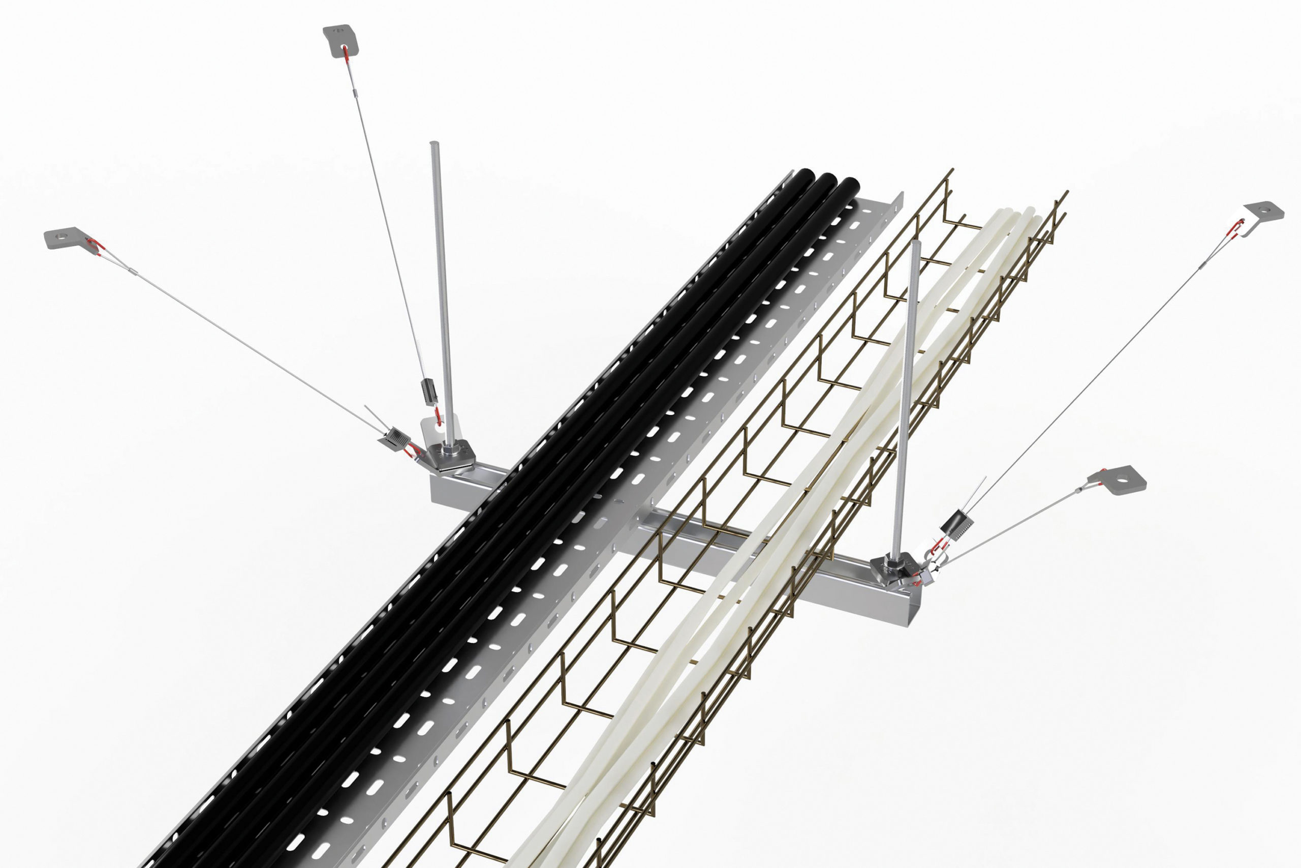
The design and installation of Zip-Clip seismic cable bracing for building services not only achieves the life-safety requirements of building codes and seismic design standards but also makes significant improvements to the functional recovery of buildings following an earthquake, by minimising seismic movement and associated damage.

 

SYSTEM DIFFERENTIATION

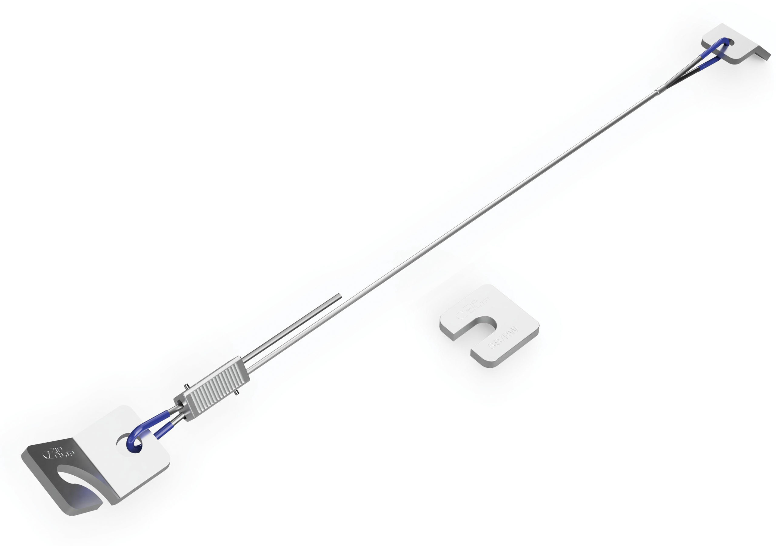
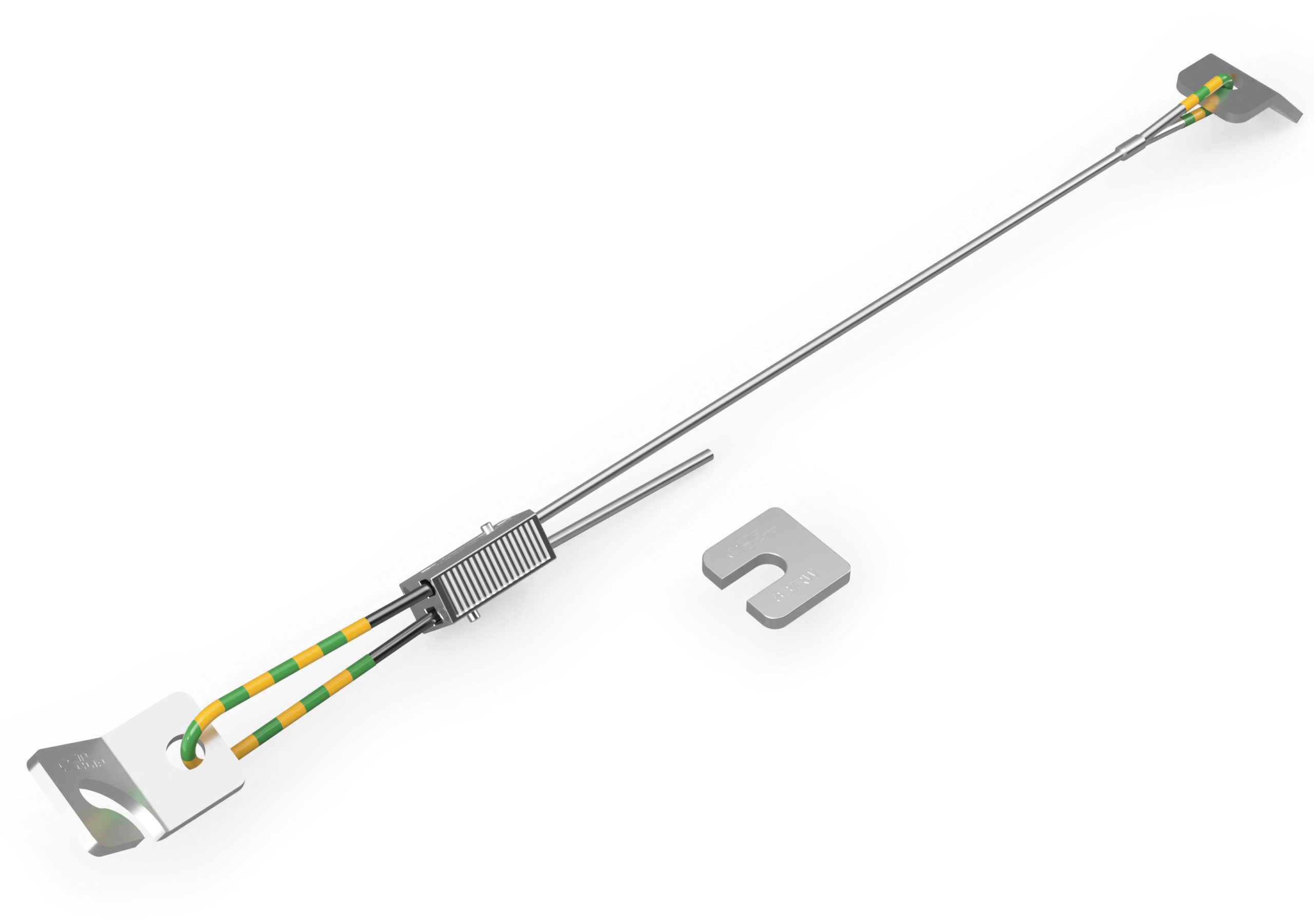
Zip-Clip Atlas seismic brace systems are colour coded to allow easy field identification, each colour representing a different increasing load-bearing capacity.

  • The R-System (RED) range of seismic braces is designed for light-duty brace applications.
  • The B-System (BLUE) range of seismic braces is designed for light/medium-duty brace applications.
  • The GY-System (GREEN/YELLOW) range of seismic braces is designed for medium/heavy-duty brace applications.

All systems can be used as a seismic brace solution for new or retrofit installations to non-structural components.

PLEASE NOTE: The selection of seismic braces requires correct seismic design. This must be carried out by a qualified structural engineer.
Installers must ensure that seismic design has been carried out prior to installation.

For details on the capacities of the different systems request a copy of our latest Design Guide by emailing seismic@zip-clip.com.


COMPONENT PARTS

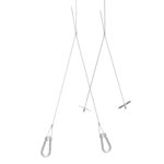
Each system is supplied as a complete kit which includes the following:

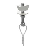
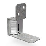
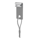
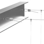
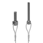
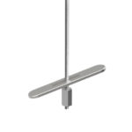
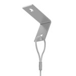
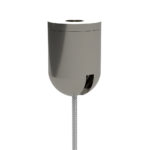
  • Seismic bracket – to anchor the brace to a supporting structure;
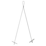
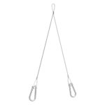
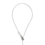
  • Wire rope – which transfers the load to the building structure;
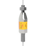
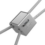
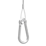
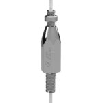
  • Zip-Clip seismic locking device – to attach the brace to the services;
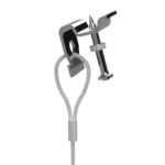
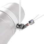
  • Retro-fit bracket – to anchor the wire rope to the primary supports;
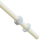
  • PVC sleeve – for ground identification and protection;
  • Seismic restraint washer – to clamp the retro-fit bracket to the services.


INSTALLATION

  1. Attach the seismic bracket to the ceiling structure with an appropriate anchor as per the manufacturers’ instructions, and structural engineers’ recommendations.
  2. Fit retrofit bracket to existing primary support. Ensure the seismic restraint washer is included, and bracket orientation is in-line with the brace.
  3. Pass wire rope through the Zip-Clip seismic locking device.
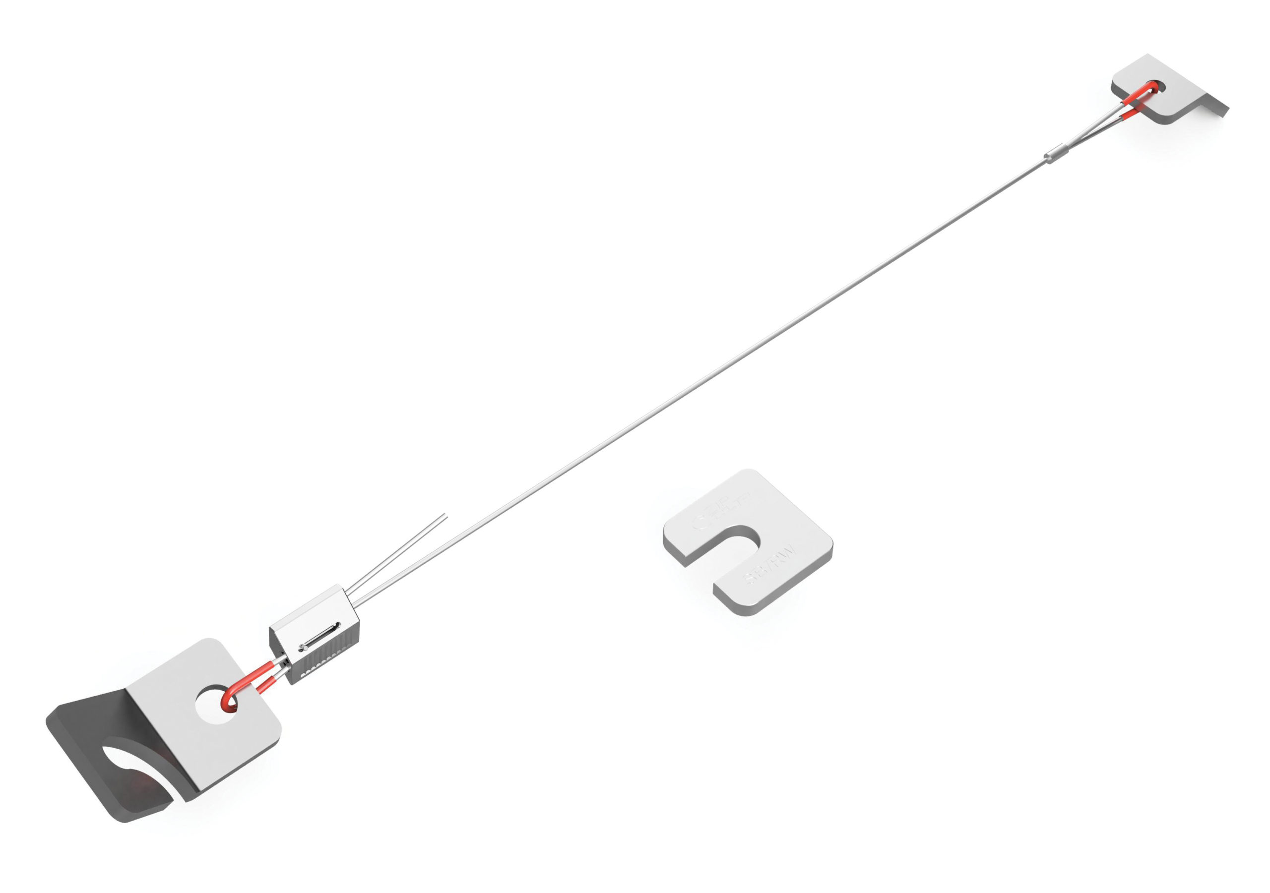
  4. Feed on additional PVC sleeve.
  5. Loop wire through the available hole in the retrofit bracket and position PVC sleeve against the through hole.
  6. Feed wire back into Zip-Clip seismic locking device.
  7. Apply tension by hand.
  8. Coil excess wire and secure to the main brace, if necessary trim excess leaving 150 mm tail.


GENERAL PRINCIPLES

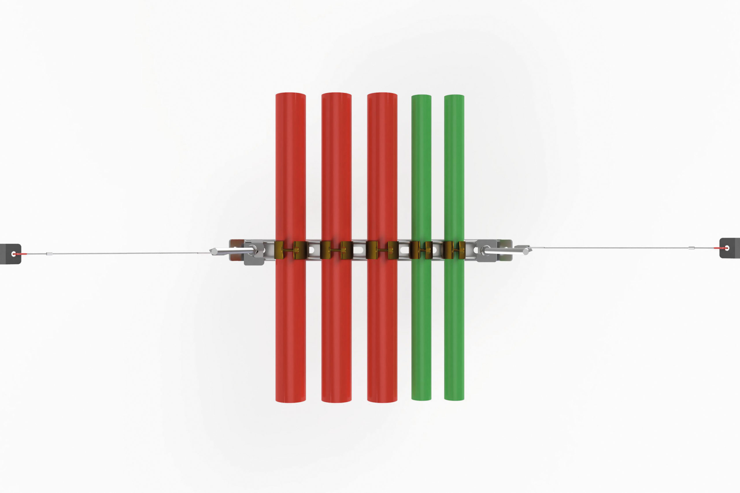
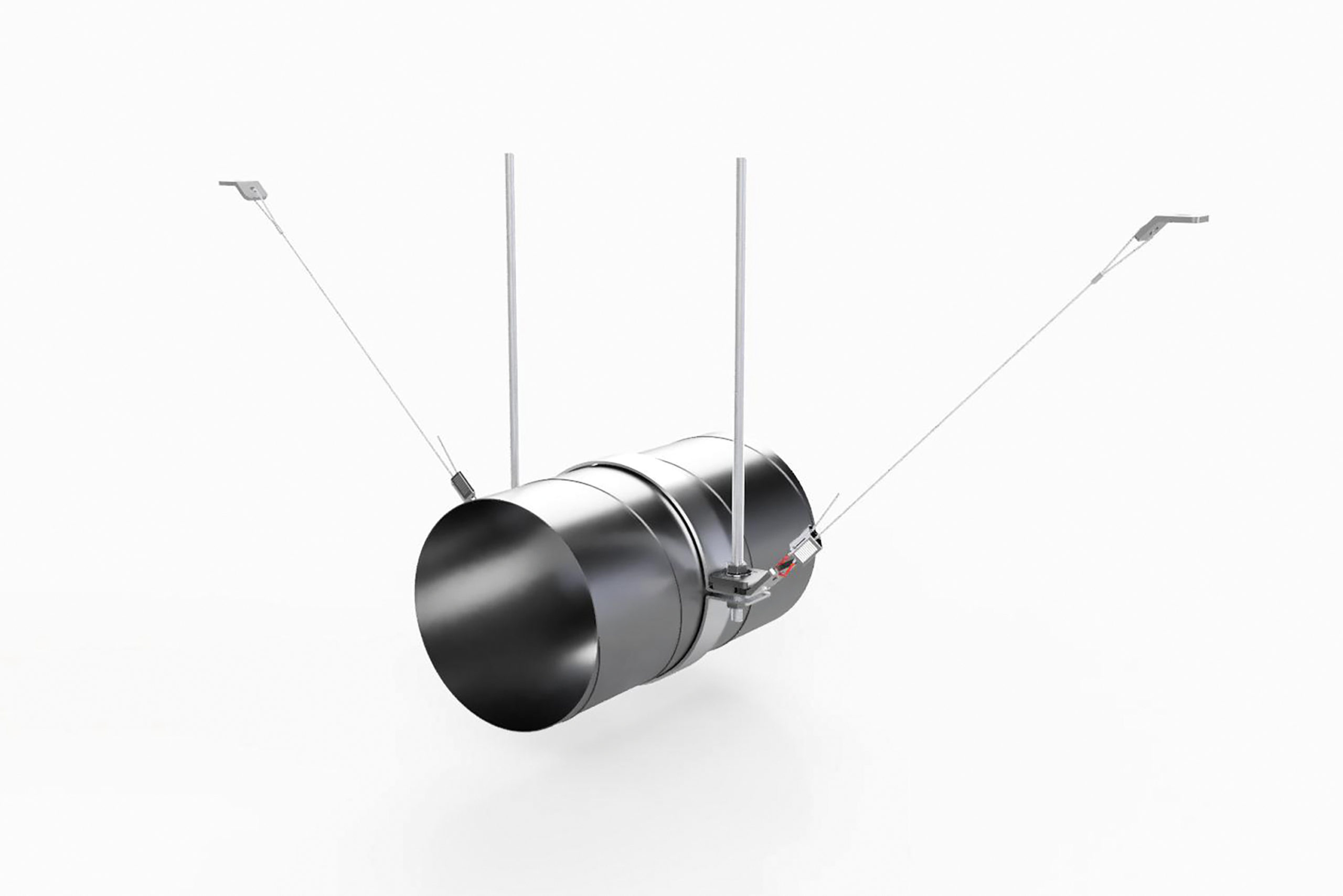
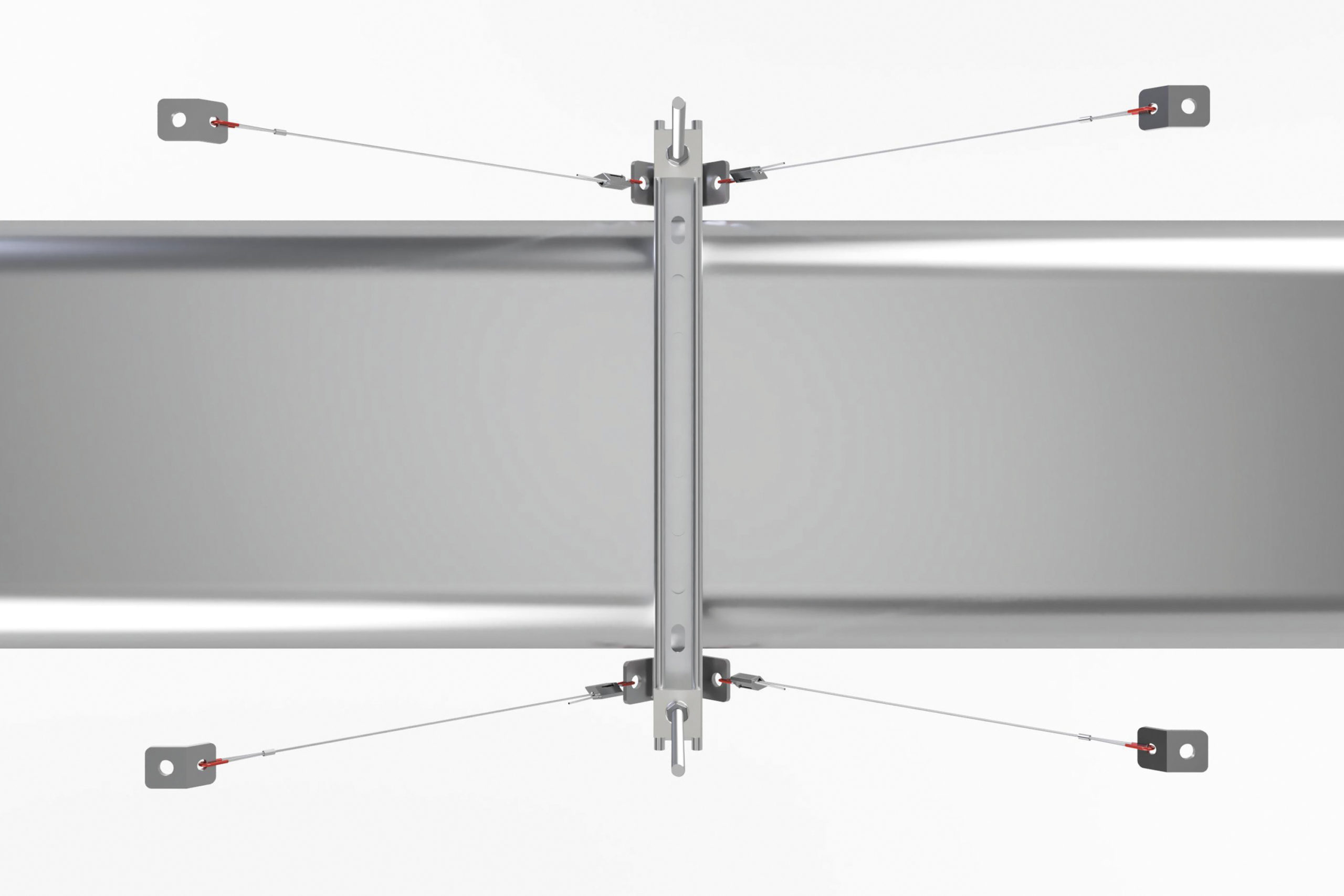
  • Braces should always be installed as opposing pairs.
  • Wire rope should not be in contact with anything along the brace length.
  • Brace angles from the horizontal should not exceed 60 degrees.
  • Anchor brackets should be installed in line with the brace.
  • Square plate washers should be utilised to secure retrofit brackets along with restraint washers where available.
  • Where no square washer is available, a seismic restraint washer must be used along with the
    retrofit bracket.


SPACING GUIDELINES

Seismic design standards require that non-structural services must be braced at regular intervals. Appropriate brace spacings must be determined by a qualified structural engineer.


ANCHORS

Connections to concrete must be designed using anchors that have been rated for use with cracked concrete and seismic loads.

Design and certification of concrete anchors needs to be completed by a qualified structural engineer.

For attachment to other ceiling structures, such as steel, an appropriate assessment of the base material capacity should be undertaken by a qualified structural engineer.


TENSION

Braces should be tensioned by hand to remove any slack until no longer possible by hand.


DATASHEET

TESTING AND CONFORMITY

STRENGTH TESTED

Zip-Clip Atlas seismic braces have been independently strength tested following ASCE 19 , ASTM A1023, ASTM A931 and NZS 4219 to determine Characteristic Break Strengths.

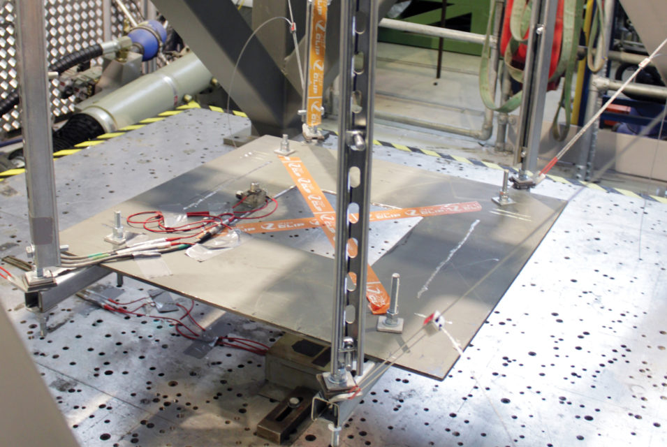
They have also been seismically tested using tri-axial shake table apparatus by Element Materials Technology at the Earthquake and Engineering Laboratory in Bristol University, UK, following ICC ES AC156 and IEEE344 – seismic qualification for equipment in nuclear power stations.

Seismically tested to:

IEEE 344-2013, standard for qualification of equipment for nuclear power generating stations.
ICC ES AC156, acceptance criteria for seismic certification by shake table testing of non-structural components.
Third-party certification is available for strength and seismic tests.


SYSTEM STRENGTHS

Advantages of wire rope seismic braces are:

  • Speed of installation and adjustment
  • The wire rope can be any length
  • Angular adjustment is very easy
  • The tensile load on the primary supports is not affected by the use of wire rope seismic braces.

CONTACT ZIP-CLIP

PRODUCT CODES

product-code description swl pack-qty ean tsi
IEEE2R 2 meter R-System seismic brace n/a 2 TBC TBC
IEEE3R 3 meter R-System seismic brace n/a 2 TBC TBC
IEEE5R 5 meter R-System seismic brace n/a 2 TBC TBC
IEEE2B 2 meter B-System seismic brace n/a 2 TBC TBC
IEEE3B 3 meter B-System seismic brace n/a 2 TBC TBC
IEEE5B 5 meter B-System seismic brace n/a 2 TBC TBC
IEEE2GY 2 meter GY-System seismic brace n/a 2 TBC TBC
IEEE3GY 3 meter GY-System seismic brace n/a 2 TBC TBC
IEEE5GY 5 meter GY-System seismic brace n/a 2 TBC TBC

Please Note: Brace lengths other than those listed are available available on request.